| Original Part | Replacement Part | Cost |
|---|---|---|
Citizen LS12T2-T |
Citizen LS12T2-T |
$0.38 |
Over the past few months, the power switch on my Nexus 5 started acting up. At first, when I pressed the power button, the phone would occasionally interpret the press as a double tap or long hold, causing the display to turn back off or show the power off dialog. Over time, this became worse, and the phone started to boot loop, randomly turning itself on and off repeatedly. It turns out that this is a known hardware issue; the power switch has reached the end of its usable operating lifetime. Although it is possible to work around this in software by remapping the power button with a custom ROM, I decided to replace the power switch and stay with the stock ROM. The cost of a replacement switch is actually less than $0.50, so I ended up paying more for shipping than for the switch itself.
Mario has detailed the process on his website, which, in summary, amounts to disassembling the phone, removing the motherboard, desoldering the broken power switch, and soldering on the new power switch. Though conceptually straightforward, performing the latter two steps are quite tricky, because the leads on the power switch are very tiny, and the metal case of the switch is soldered through-hole directly next to a PCB shield on the other side of the board.
To avoid accidentally touching other components on the motherboard with my soldering iron, I masked off the area next to the switch with polyamide (Kapton) tape, which can withstand over 700°F without melting. Since I don’t have hot air rework equipment, I used a regular temperature-controlled soldering iron, and desoldered the switch by adding solder behind it until I formed a big blob that touched all five pads, allowing it to freely slide off. To clean the two through-hole pads, which provide mechanical support for the switch, I added low-melting indium-based point solder (e.g. ChipQuik) and used solder wick.
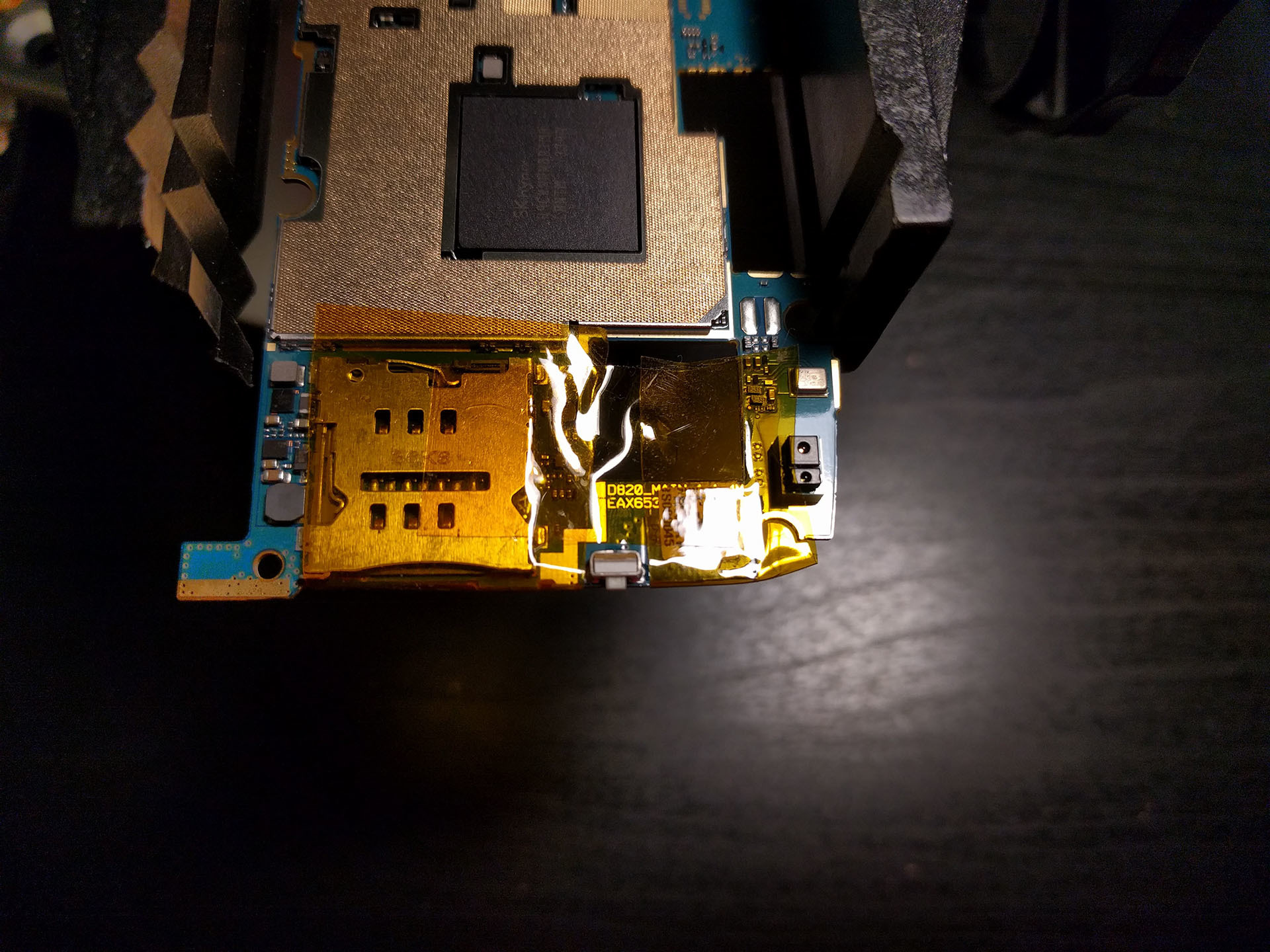
Top view of motherboard, masked with polyamide tape
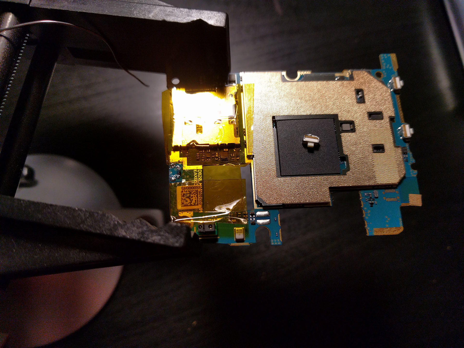
Top view of motherboard, after desoldering old switch
Before soldering on the new switch, I added extra liquid flux to avoid accidentally bridging any of the switch contacts with the shield, since they are very close. Then, after soldering on the new switch, I cleaned off the flux residue with isopropyl alcohol. Finally, I had to carefully unpeel the polyamide tape to avoid tearing off the manufacturing data matrix code.
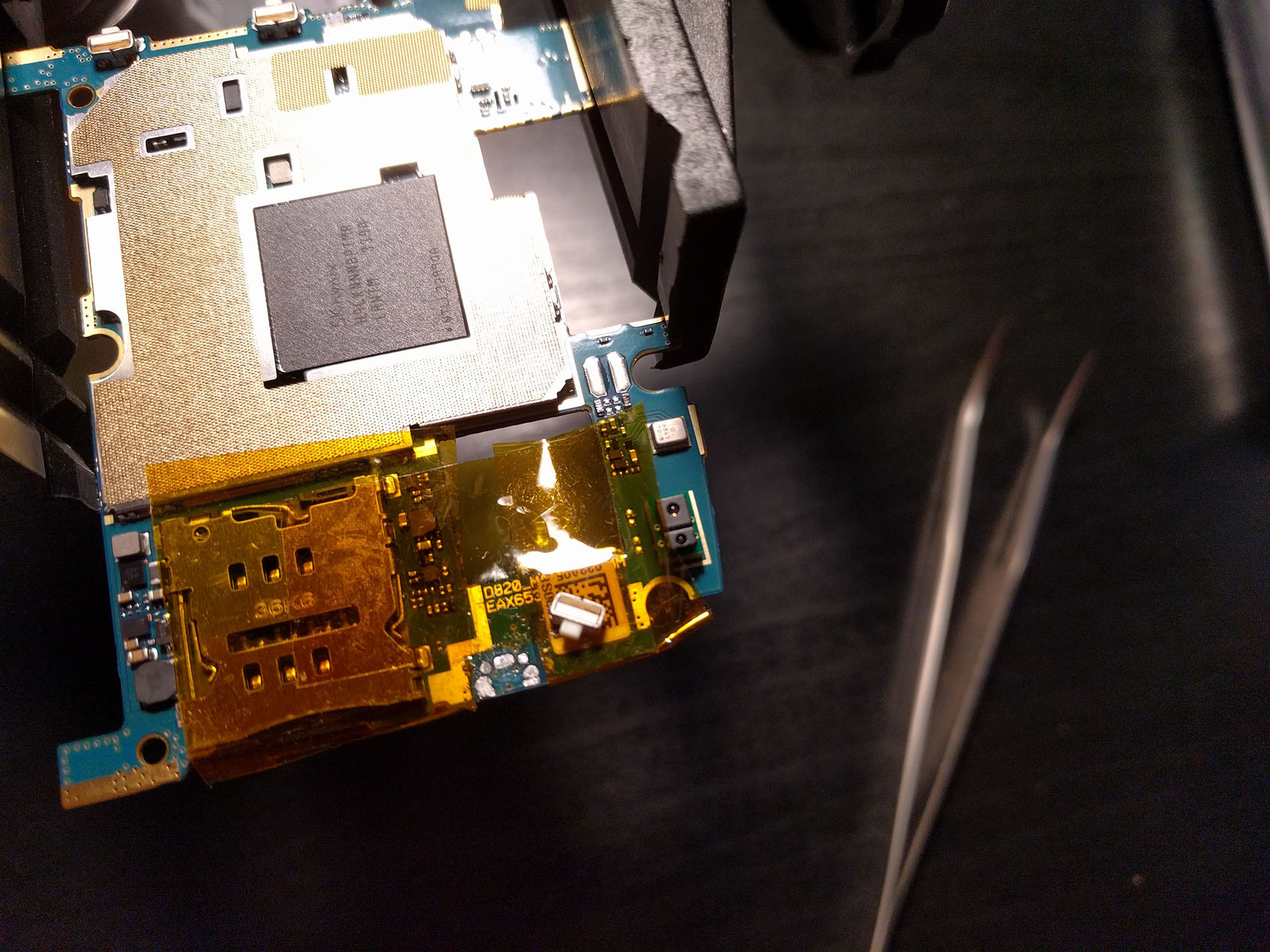
Top view of motherboard, after cleaning with solder wick
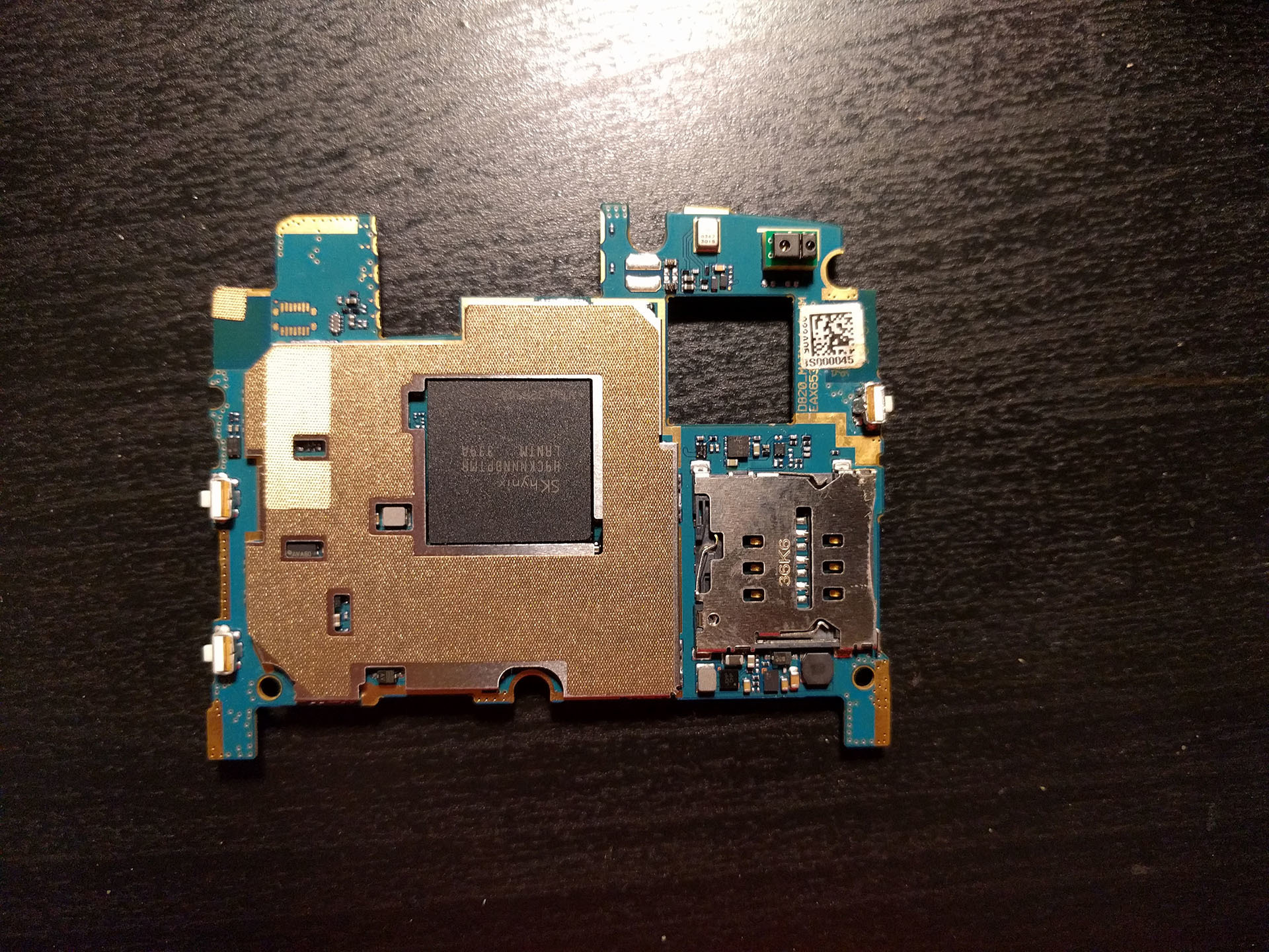
Top view of motherboard, after switch replacement
The switch is rated for over 100,000 cycles, and I was curious to see how it worked internally, so I cut the broken one apart. The plastic body of the switch is encapsulated by a metal shield, which provides mechanical support. On the front face is a plastic actuator, that is backed by polyamide film, presumably to provide dust and water-proofing. Behind that is a metal foil that deforms and clicks to provide tactile feedback, making contact with another metal foil on the underlying brown epoxy laminate, which is soldered to the PCB on its backside.
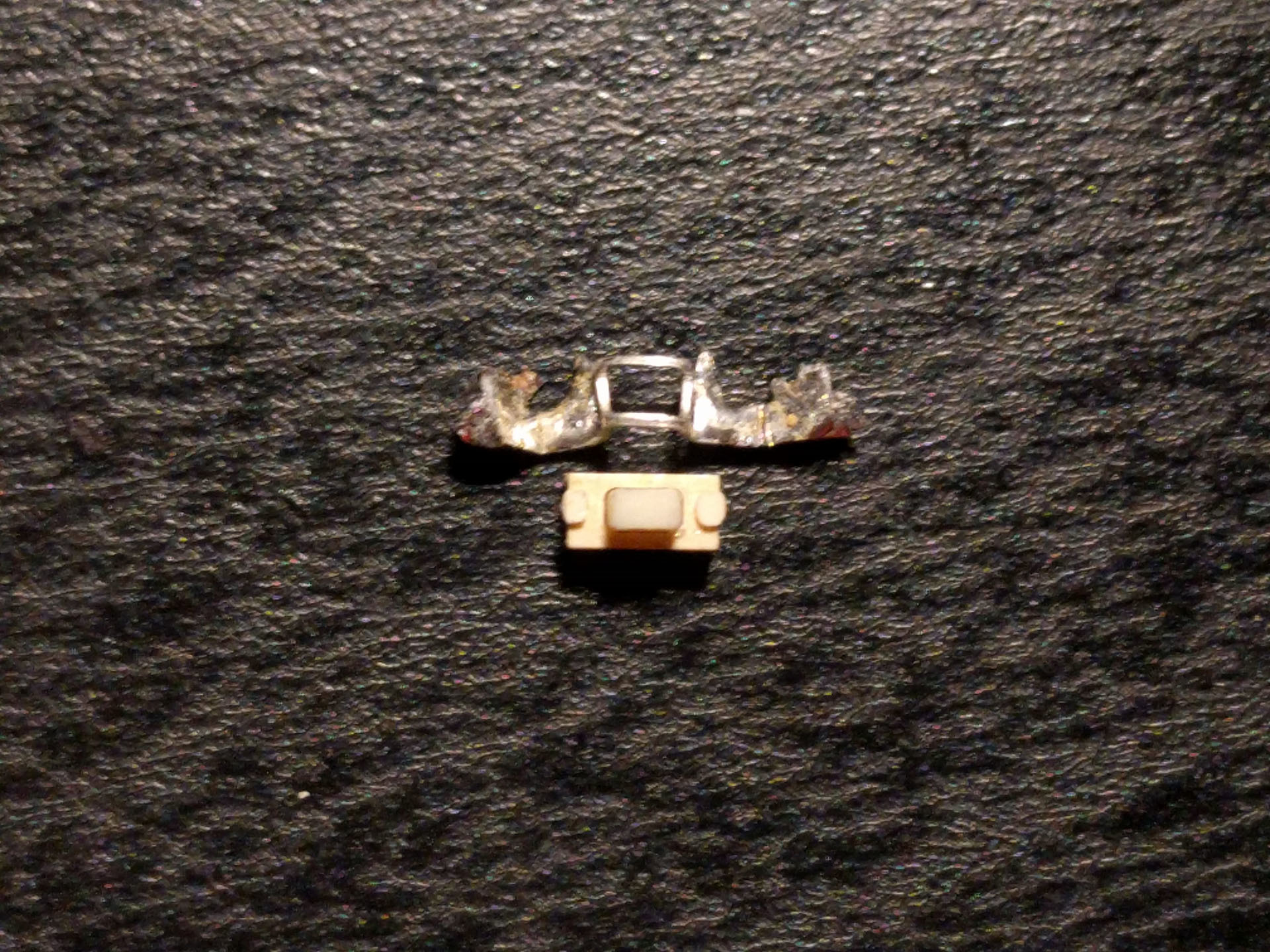
Front view of switch, with metal shield removed
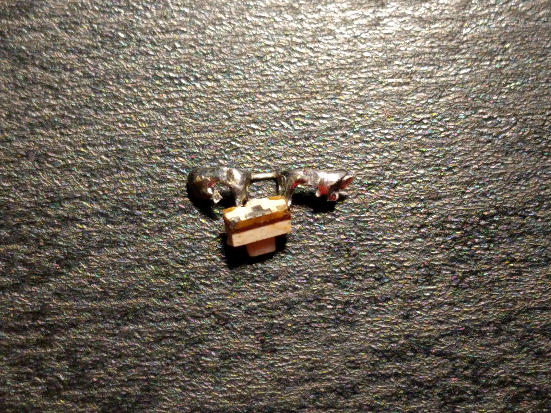
Back view of switch, with three surface-mount contacts (one missing)
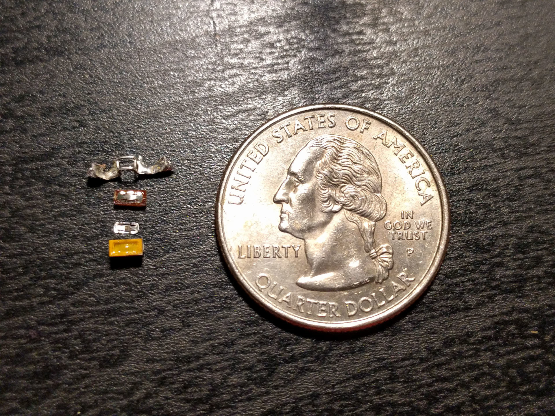
Top view of disassembled switch, with shield, metal foil, epoxy laminate, polyamide-backed actuator, and quarter for scale