| Label | Original Part | Replacement Part | Cost |
|---|---|---|---|
| R465 | 200 kΩ, SMD 1206 | KOA Speer RK73H2BTTD2003F |
$0.11 |
| Front Window | Agilent 34410-49321 |
Keysight 34410-49321 |
$7.47 |
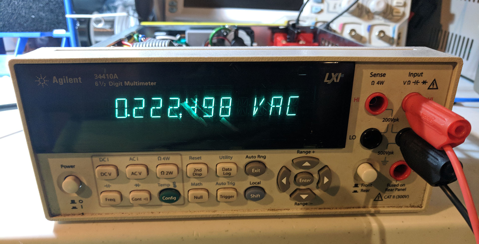
Erroneous measurement of 5Vac, with damaged display
Recently, I acquired a partially operational Agilent 34410A multimeter. Although it passed self-test, all AC voltage measurements were wrong, and two-wire resistance measurements exhibited approximately 3Ω offset even when shorted. But when measuring from the rear of the unit, or in four-wire measurement mode, this offset disappeared. Luckily, a schematic for this model is available, which simplified the debugging process. Given that the display on this unit was also damaged, I also took this opportunity to replace it.
Problem #1: 2W Resistance Offset
The offset only appeared when measuring from the front of the unit, suggesting that the fault must be input-specific, and not part of the current source, input amplifier, or analog-to-digital converter circuitry. But according to the schematic, the front panel measurement path is directly connected to S100, the front/rear switch that multiplexes these signals together. When measured using another multimeter, the resistance of the front panel input path up to the front/rear switch was less than 1Ω, suggesting that the fault was elsewhere.
On the older 34401A multimeter, the front/rear switch is a known source of flaky measurements, as debris or oxidation can build up inside the switch, obstructing the contacts. As suggested on the EEVBlog forums, it is much easier to disassemble the switch and clean it with e.g. CAIG DexIT D5 than replace the switch, since the S100 C&K / Schadow F8UEE part can be difficult to source. After carefully retracting the actuator spring and extracting the center pin, the plastic retaining clip on the top of the switch can be lifted using a tweezer, allowing the body of the actuator to slide out. Care must be taken to avoid losing the actuator contacts or springs during this process, as they can easily loosen and fly away. But, cleaning the front/rear switch didn’t have any effect, suggesting that the problem was likely digital, rather than analog.
The 34410A multimeter supports a source-specific digital zero offset calibration, as detailed in the service manual. If the calibration was performed with a high-resistance short across the input terminals, then subsequent measurements would include this incorrect offset. It turns out that certain units, including this one, were miscalibrated at the factory, as detailed in Service Note 34410A-02. The solution is to simply connect a calibration short to the front panel and rerun zero offset calibration, which eliminated the offset.
Problem #2: AC Voltage Measurements
As for the incorrect AC voltage measurement, the fault must be localized to the AC signal conditioning path, because all other measurements are correct, indicating that the analog-to-digital converter is fully operational. At a block diagram level, the input AC signal is attenuated, amplified, and then passed through an anti-alias filter before entering the analog-to-digital converter. Since these erroneous measurements occur on all AC input ranges (100mV, 1V, 10V, 100V, and 750V), the fault is likely in the attenuator. The schematics show the AC signal is attenuated with 1 MΩ of input impedance, then amplified with a single Analog Devices AD825AR operational amplifier in an inverting configuration to produce -0.2 gain. Due to limitations of dielectric breakdown voltage for surface-mount resistors, five 0.2 kΩ resistors are connected in series to form the 1 MΩ input impedance, at up to 750 Vrms / 1000 Vpk. Measuring each separately reveals that the first input resistor R465 has gone open circuit, resulting in unintentional parasitic coupling that produced incorrect readings.
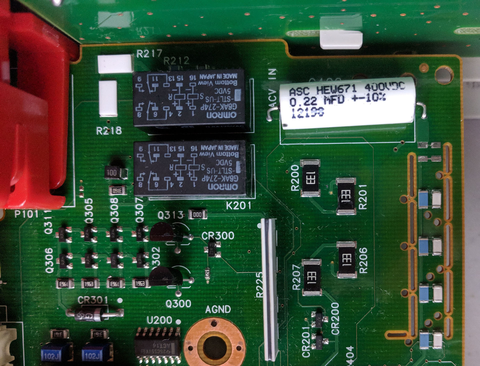
Removal of C465 and R465, top right
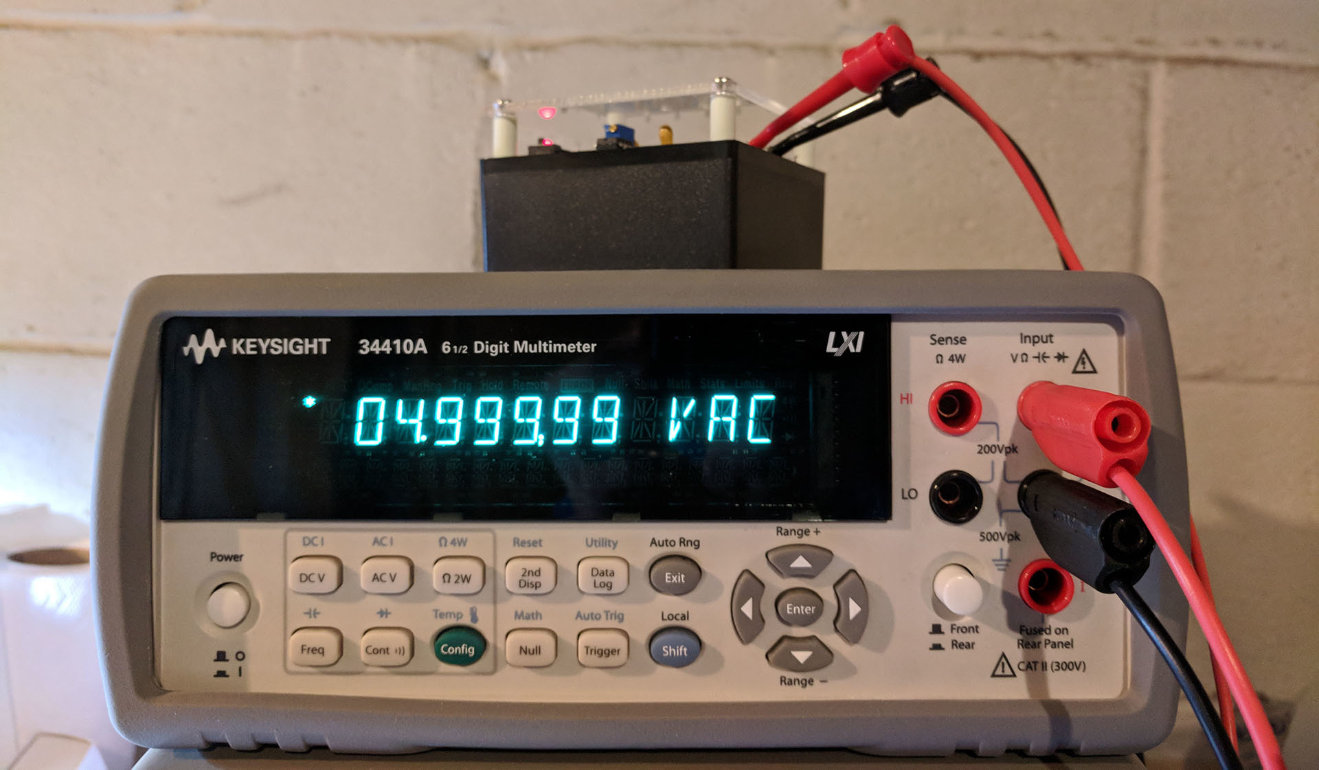
Correct measurement of 5Vac, from a calibrated DMMCheck Plus