Update (December 2019): Schematics/layout, and model drawings/assembly are available online.
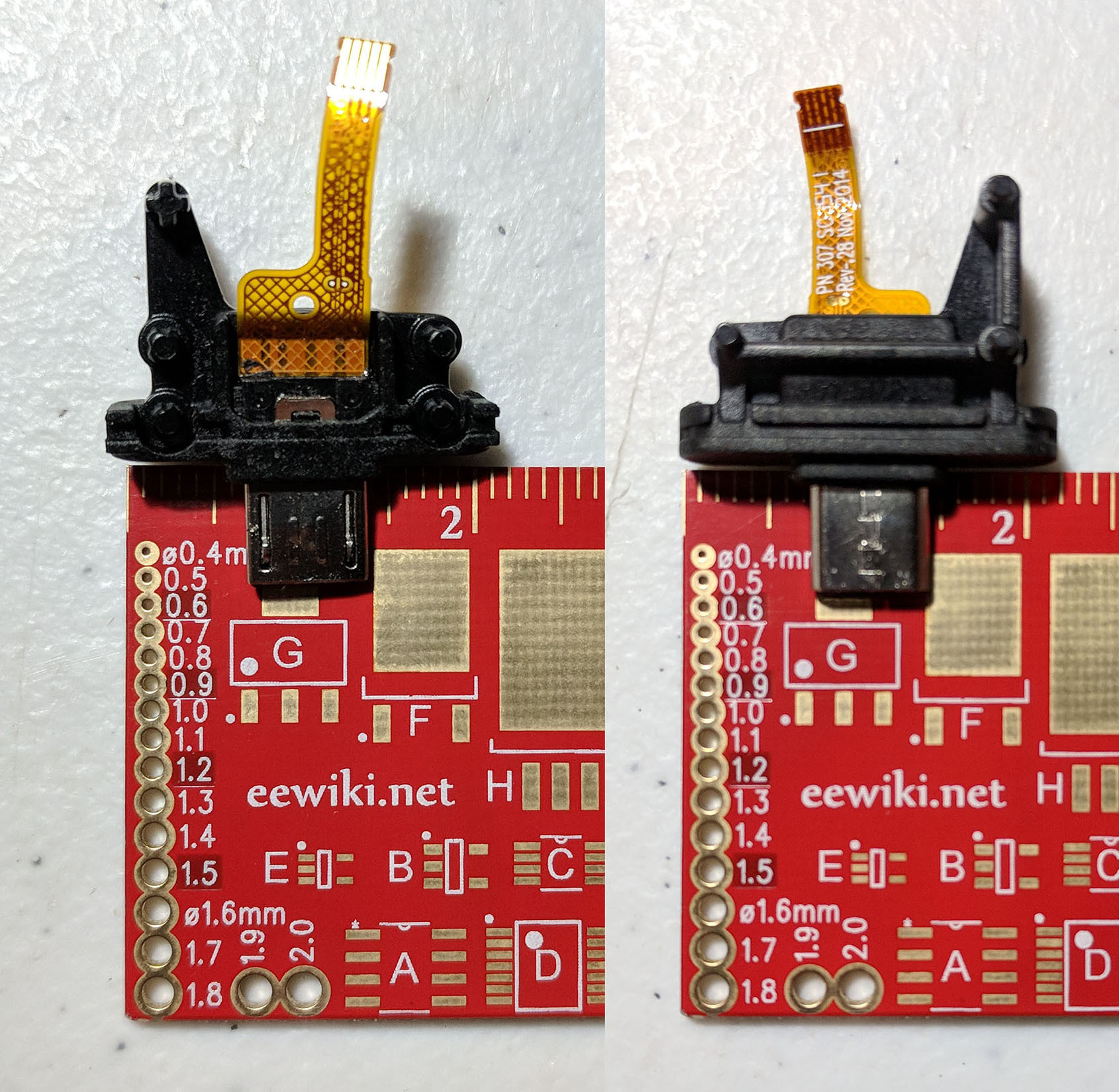
Top-down (left) and bottom-up (right) views of the original connector assembly
A while back, I picked up a Seek Thermal Compact smartphone thermal imaging camera with a broken USB mini-B plug. After disassembling the unit, I discovered that the connector assembly uses injection-molded plastic, making it virtually impossible to just replace the broken plug. As a result, I decided to design and create my own replacement connector assembly using 3D printing, which I haven’t tried before. Additionally, I switched to a USB type-C plug, which is natively supported by my phone. Surprisingly, Seek themselves do not offer a model with USB type-C, only one with a Lightning plug for Apple devices, and one with a USB mini-B plug for Android devices.
Electrical
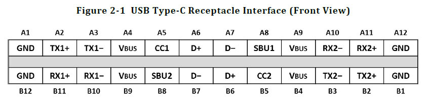
Pin assignments for the reversible type-C connector from the specification
Although the type-C connector is backwards-compatible with previous versions of the USB interface specification, it also supports newer features such as Power Delivery, SuperSpeed, Alternate Mode, Debug Accessory Mode, Audio Adapter Accessory Mode, etc., and thus requires additional signaling to select the correct operation. Additionally, the type-C connector supports dual role, meaning that the same connector can be both a power source or sink, and a data upstream facing port (host) or downstream facing port (device). Unlike with previous connectors, type-C allows these power and data roles to change independently, regardless of the connector shape. This is implemented by connecting resistors with special values to the configuration channel CC to select the correct role.
Since this can be quite confusing, here are some examples:
- Suppose you connect a smartphone to your laptop. Your laptop is charging your phone, so it is the power source and your phone is the power sink. Your laptop can communicate with multiple phones connected at the same time, but your phone can’t connect to multiple computers at the same time, so your laptop is the data host, and your phone is the data device.
- Now, suppose you connect a keyboard to your smartphone. Your phone is charging your keyboard, so it is the power source and your keyboard is the power sink. Likewise, your phone is the data host, and your keyboard is the data device. Notice that this is the reverse of (1), indicating that your phone is a dual role device.
- Ok, now you connect your laptop to your docking station. Your docking station is charging your laptop, so it is the power source, and your laptop is the power sink. But, your laptop is still the data host, and your docking station is the data device. Notice that the power and data roles are swapped, unlike (1) and (2).
USB type-C: Power
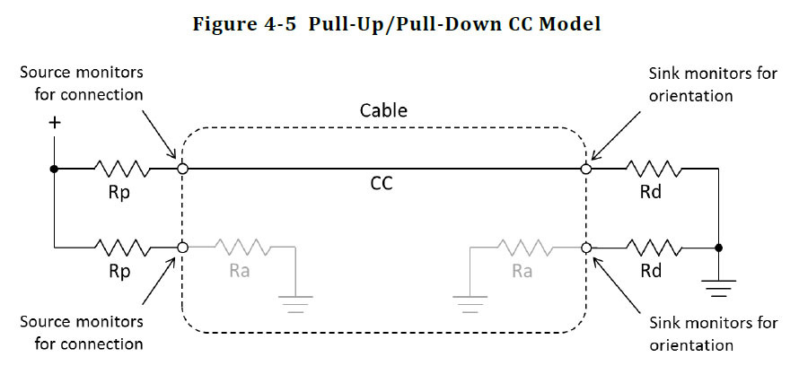
Depiction of the pull-up/pull-down model from the specification
Since a device needs to be powered before it can communicate, the power role needs to be determined first by measuring the voltage drop on CC. This is typically depicted using the pull-up/pull-down model, where the source connects a pull-up resistor Rp from VBUS to CC, and the sink connects a pull-down resistor Rd from CC to GND. Since a source may be capable of only supplying a limited amount of current, typical values for Rp (assuming 5V VBUS) can vary from 56kΩ ± 20% for default USB power (depending on version), to 22kΩ ± 5% for 1.5A, to 10kΩ ± 5% for 3.0A. In contrast, Rd is typically fixed at 5.1kΩ ± 20%, and Ra must be between 800Ω - 1.2kΩ during connection detection, but isn’t needed for legacy devices. Note that because the type-C connector is reversible, there are two pins CC1 (top) and CC2 (bottom).
USB type-C: Data
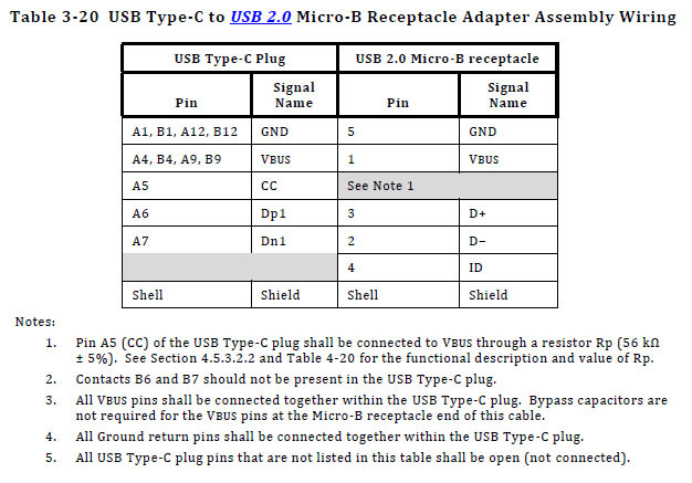
Wiring diagram for a type-C to USB 2.0 micro-B receptacle adapter assembly from the specification
For data, because the Seek Thermal Compact is a legacy USB 2.0 device, only the D+/D- data pins need to be connected to the type-C connector, with the remaining SBU and TX/RX pins left disconnected. Helpfully, the type-C specification provides definitions for various legacy cable assemblies, including a USB type-C connector to USB 2.0 micro-B receptacle, shown above. Note that only one pair of D+/D- signals needs to be routed to the type-C plug, because the type-C receptacle is responsible for routing signals to both pins, in case the cable is reversed. Since the Seek unit natively ships with a micro-B plug, it would appear that this diagram is sufficient for building a replacement with a type-C plug.
Actually, this diagram is misleading, because the Seek unit isn’t a standard USB device, but rather a USB On-The-Go B-device. Before the advent of USB type-C, USB OTG was developed as a USB 2.0 supplement in order to allow certain devices (e.g. smartphones) to function as dual-role devices, using a special micro-AB receptacle and a special ID pin, shown below.
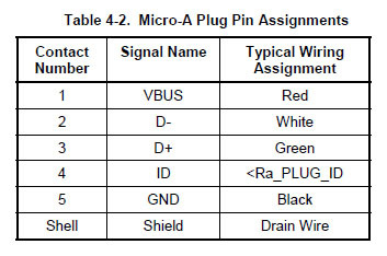
Pin assignments for the micro-A connector from the specification
As a result, though the micro-B plug suggests that the Seek unit is a regular data host and power source, it is actually an OTG B-device, which is a power sink and data device. Instead of connecting Rp (56kΩ) between VBUS and CC as shown on the wiring diagram, Rd needs to be connected between CC and GND.
Interface Board
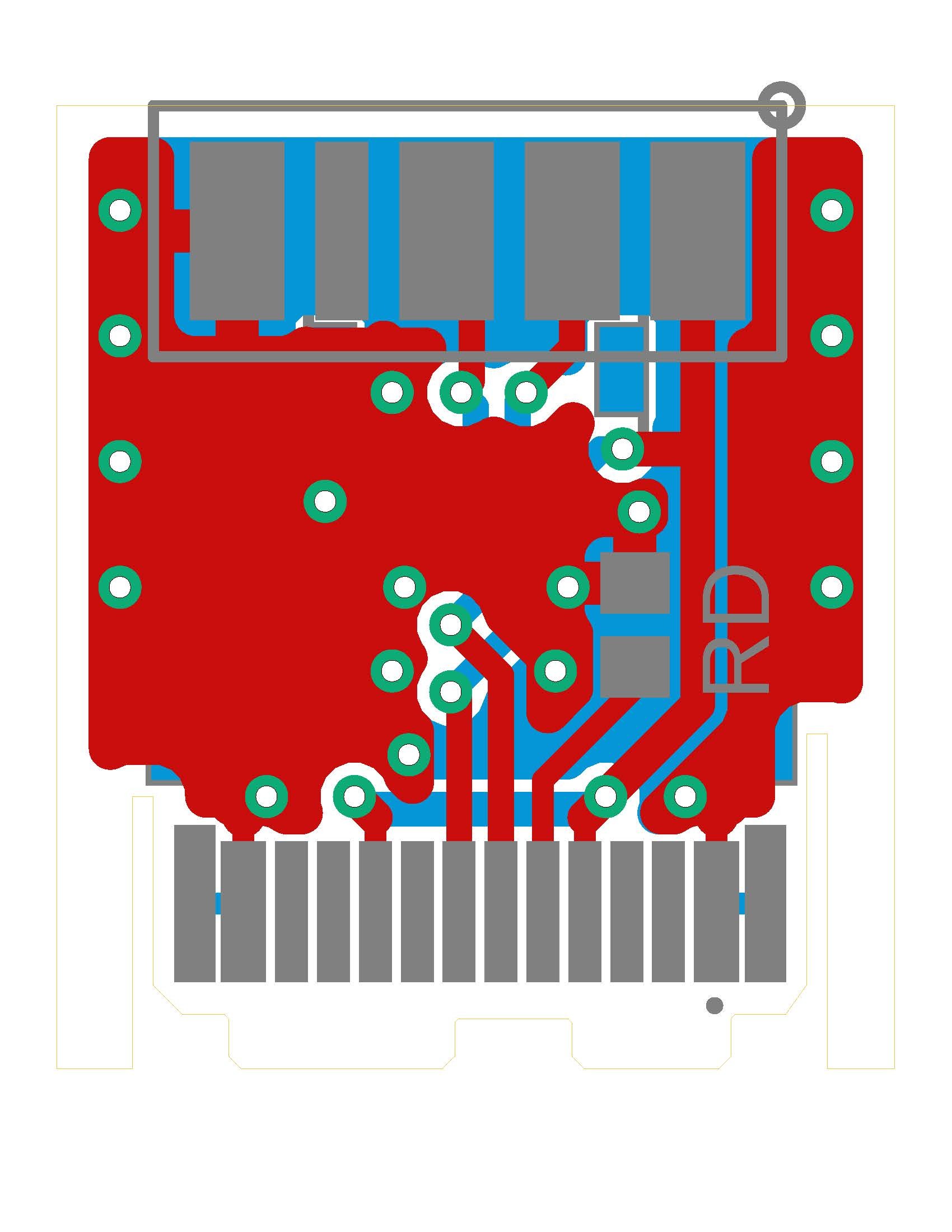
Layout (v2.1)
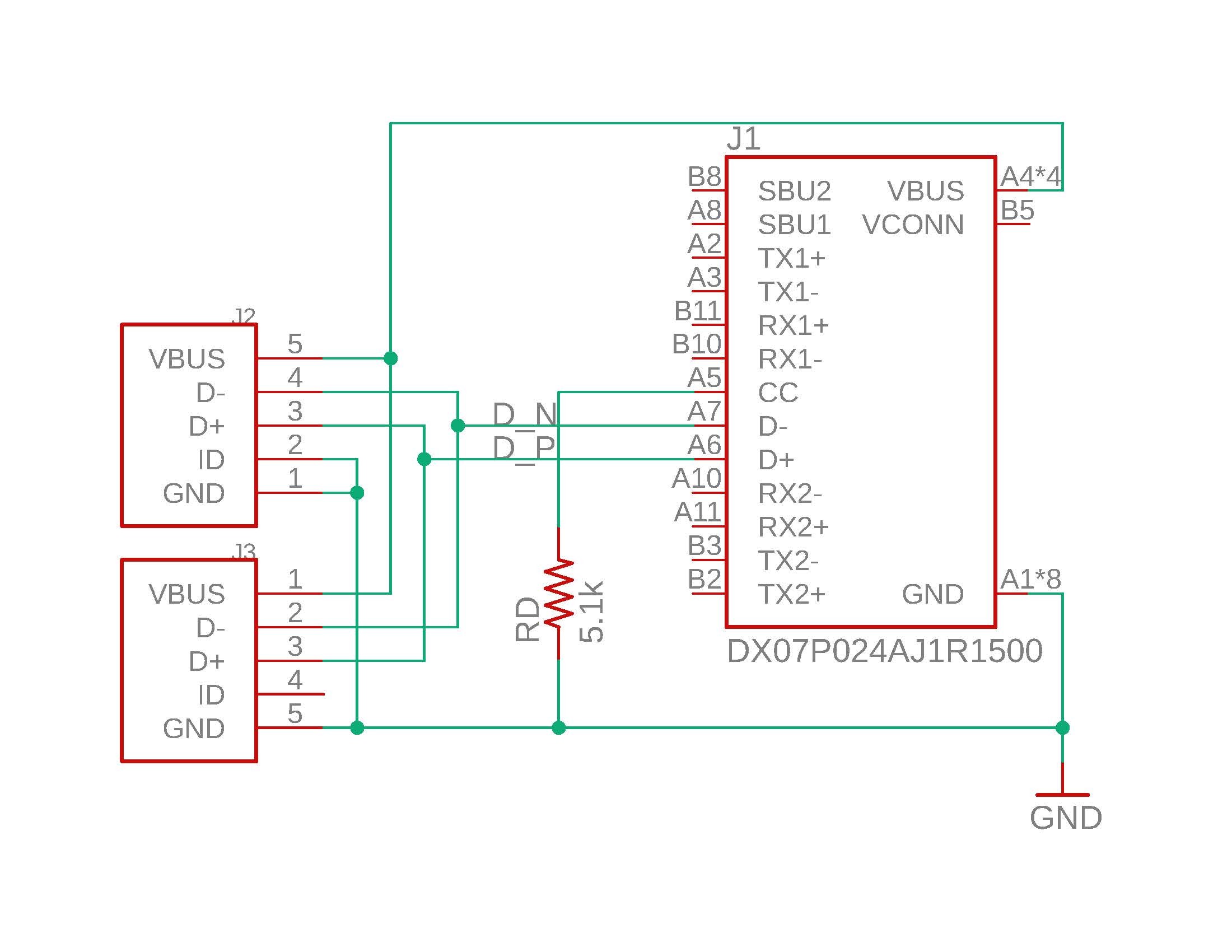
Schematic (v2.1)
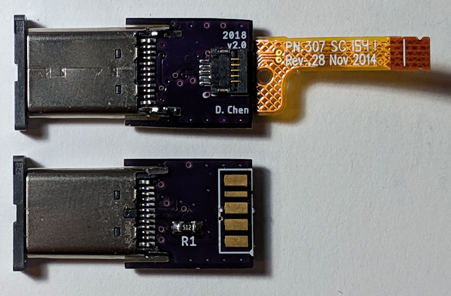
Photo of a fully populated (top) and partially populated (bottom) interface board (v2.0)
Putting all of this together produces the above type-C interface board, with schematic, layout, and assembled photo shown. Two USB footprints are included, depending on whether the flexible printed circuit (FPC) can be reused from the original cable assembly on J3, or a substitute flat flexible cable (FFC) needs to be connected to J2. Since the ID pin is internally connected to GND on the FPC, it needs to be explicitly connected on the schematic for the FFC. Care has been taken to match trace lengths on the D+/D- differential pair to minimize propagation skew, but it is difficult to ensure 90Ω trace impedance on 0.8mm FR4 substrate. With revision v2.0, I corrected the aforementioned mistake with Rp and Rd, and with revision v2.1, I moved Rd and changed its footprint from 0603 to 0402.
Mechanical
Aside from building the type-C interface board, I also needed to design a replacement plastic assembly that could fit it.
Modeling
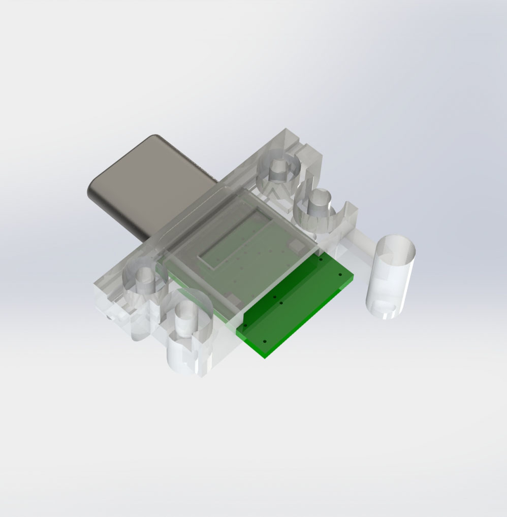
Top-view render of the completed assembly
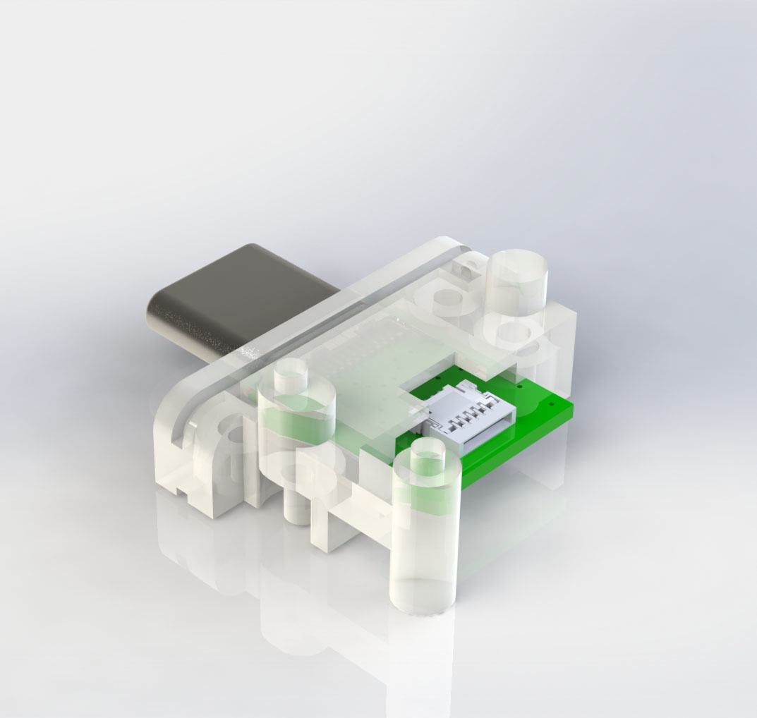
Bottom-view render of the completed assembly
Initially, I started by measuring various dimensions of the original connector assembly using calipers, then redrawing them to build a replacement in SolidWorks. Typically, this process involves creating 2D sketches that are anchored with respect to various geometric references (e.g. points, planes, edges, etc.), and then extending them into 3D features using built-in operations (e.g. extrude, cut, fillet, etc.). Through incremental composition, this forms a complete 3D model that represents a single part, which can itself be composed with other parts through mating relations to produce an assembly. At any point in time, this construction timeline can be modified, allowing new modifications to be introduced, with subsequent changes propagated on top. This resembles a version control system for source code, where new commits can be introduced at any point in the commit history, and subsequent commits rebased on top. Having never used SolidWorks before, I made many mistakes, and needed to revise my design multiple times.
To verify correctness of the final type-C assembly, I was able to export a model of the interface board from Autodesk EAGLE in IDF 3D format, and then import it as a subassembly into SolidWorks using the CircuitWorks plug-in. Simultaneously, I was able to import vendor models for the FFC and USB type-C connectors into the subassembly. Final renders of the completed assembly are shown above.
3D Printing
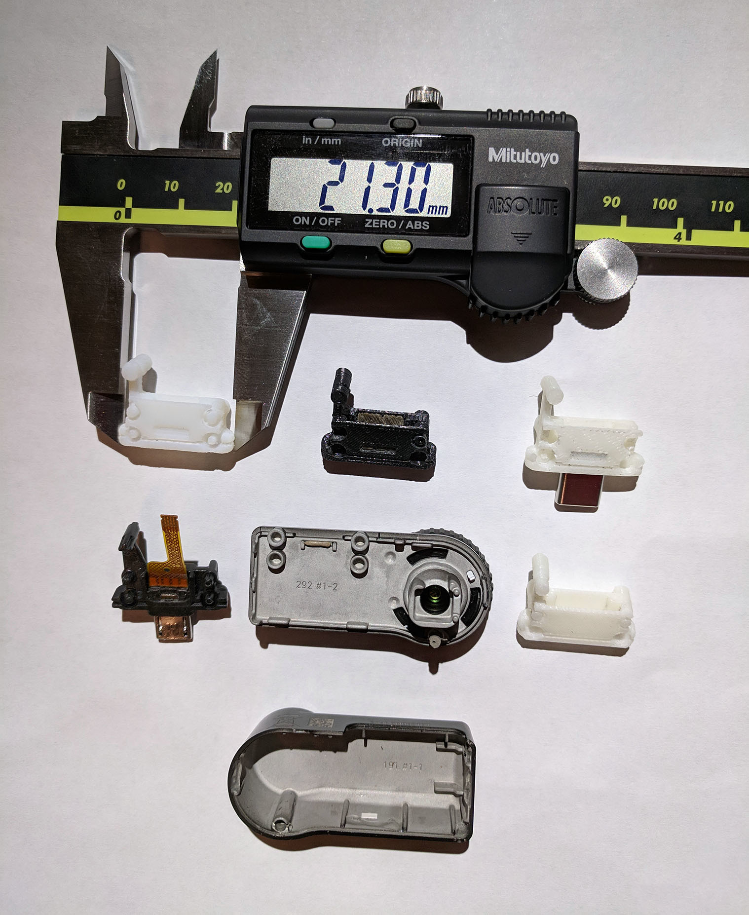
Disassembled Seek unit with test prints from various 3D printers
I had some difficult creating a design that could be easily printed and assembled, due to the size of the model and its sub-millimeter features. In particular, the interior needed to be hollow to fit the interface board, which complicated the printing process. Most 3D printers utilize fused deposition modeling, which incrementally prints an object from the ground-up using plastic filament. During the printing process, slicing software needs to introduce support material to prevent the model from collapsing due to voids or elevated features, but then this material needs to be removed in post-processing. Typically, this is facilitated by minimizing the amount of contact introduced between the object and support material, and certain printers may even support printing with special dissolvable plastic for the support material.
This is shown in the above image, where the three white-colored prints were produced using removable supports, and the middle black-colored print was produced using dissolvable supports. The rightmost two white-colored prints were produced using ABS plastic on a Stratasys Continuous Build printer, whereas the leftmost white-colored print was produced using VeroWhitePlus on a Stratasys Objet30 printer, and the center black-colored was produced using ABS plastic on a Stratasys Dimension Elite printer. Unfortunately, all of these prints suffered from various problems; the rightmost two white-colored prints were quite brittle, structurally weak, and easily damaged by support material removal. Likewise, despite the water-soluble support material, the middle black-colored print still required manual processing for complete removal, and also suffered from structural damage. Perhaps the best was the leftmost white-colored print, which preserved all four mounting pins, unlike the others, and was also both strongest and most flexible. But, all of these prints were rather imprecise, and suffered from large tolerances; for example, the USB type-C connector didn’t always fit through the front slot, and the interface board occasionally didn’t fit when inserted from the back.
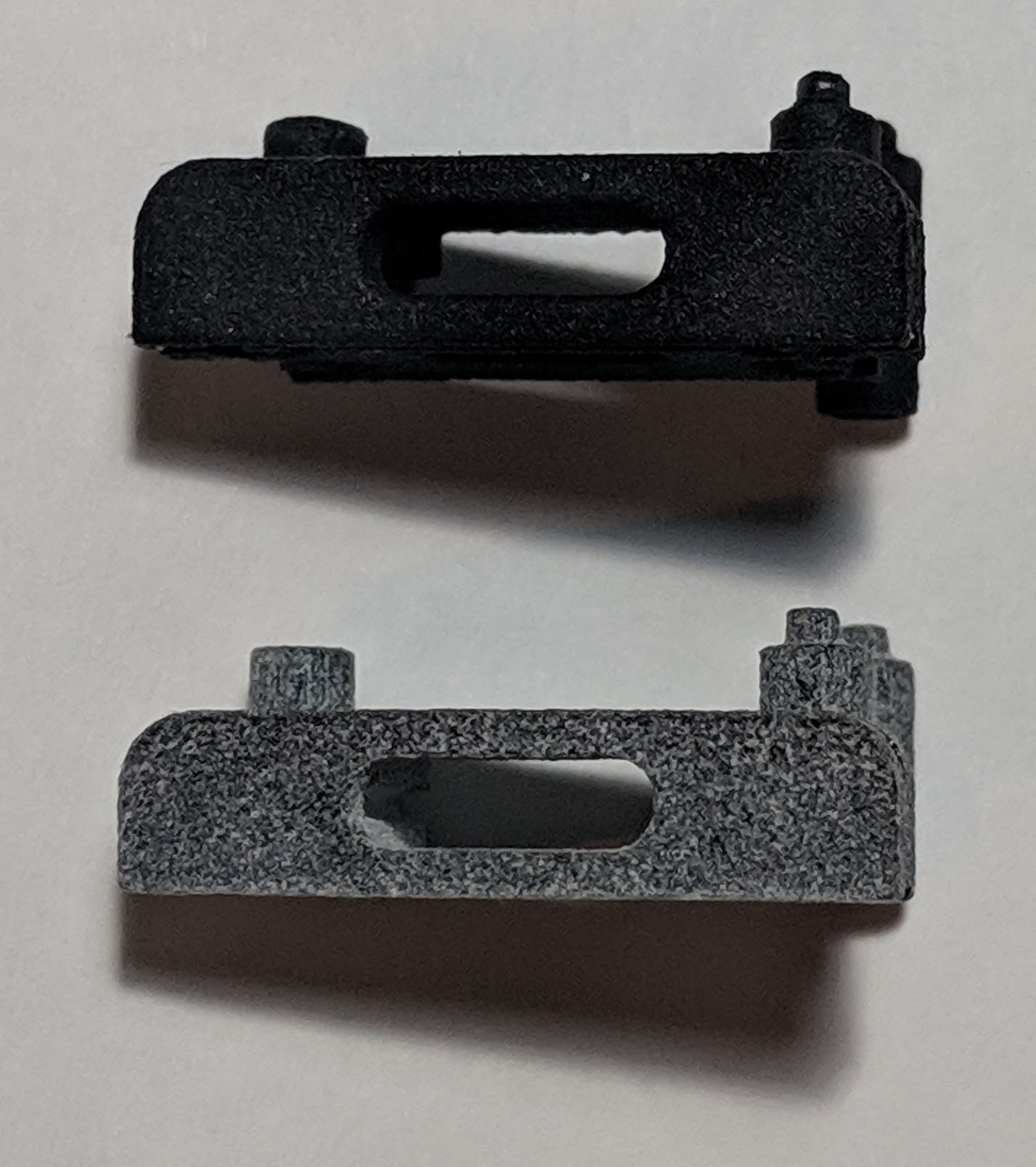
Photo of the final prints from Shapeways (top) and Sculpteo (bottom)
Overall, this entire process involved multiple iterations of modeling, printing, and testing, not only due to printing issues, but also from measurement errors and bad designs. Though these prints were useful for prototyping and validation, I soon realized they weren’t up to par for the final assembly. Although I had access to other 3D printers, such as the NVBots NVPro and Ultimaker 3 Extended, those were not recommended due to even worse accuracy and resolution. Instead, I had the final prints produced externally by commercial vendors, and I tested both Shapeways and Sculpteo. Due to process constraints on minimum wall thickness for this design, both companies could only utilize a HP Multi Jet Fusion printer, which uses a powder-bed fusion printing process. Unsurprisingly, the quality of the final print was essentially identical between both companies, as shown above. In terms of cost for black-colored prints, the closest that Sculpteo could offer was a gray-colored print followed by an expensive dyeing step in post-processing, whereas Shapeways could print directly with black-colored plastic. Shown below is the final assembled unit.
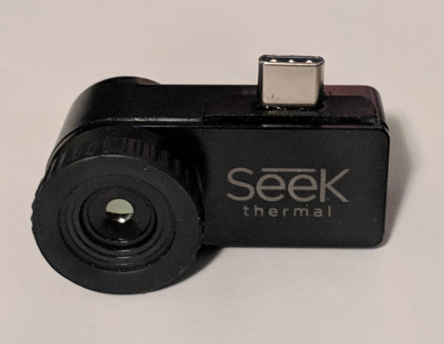
Final fully-assembled Seek unit with USB type-C connector